
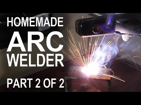
in part one of this project we scavenged
some parts from household appliances and
modified them so we could weld metal in
this project we’ll be rigging up the
electrical system and adding some
finishing touches so that our homemade
stick welder is ready for operation
[Music]
I started this project with a scrap
piece of 3/4 inch plywood that I had
leftover from the router table project
and since we have a router table
let’s profile the edges with a beading
bit just because we can next let’s cut a
piece of 2×2 and screw it in from the
bottom so that it’s secured in the
center and about 1 inch from the edge
we’ll also need to drill a couple of
pilot holes in the top because this is
where we’ll be attaching some copper
lugs to make these we simply take a
piece of half-inch copper tubing and use
a hacksaw to cut 2 inches from the end
half of the tube can be placed in the
jaws of a bench vise and when the vise
is closed with a significant amount of
force you can see that we’re left with a
nice flat end let’s place that on
another piece of scrap wood and drill a
5/32 inch hole so that it penetrates
through to the other side I’ve done this
with four different pieces and to clean
up the rough metal Barb’s I’m using a
belt sander to gently follow at the
edges until it looks a little more
user-friendly this lug here is going to
attach to a five foot length of 8 gauge
cable this was leftover from when we
wound our coils
we’ll just need to strip about two
inches of insulation from the ends to
expose the copper wire then bend the
wire over with a pair of pliers to form
a little loop the exposed copper loop
can be slid inside the casing and to
make this a permanent connection
let’s crimp it onto the cable using the
bench vise like we did before this
connection isn’t coming apart and should
easily handle the high currents that
we’ll be exposing it to
the other end of this cable will be our
ground clamp I got this metal clamp for
99 cents and with the rubber tips
removed
it’ll conduct electricity i crimped a
piece of copper tube to the end of the
wire and secured it to the clamp with
the screw the spring and the clamp is
surprisingly powerful it bites down with
a good amount of pressure and that’s
what we’ll need for making a firm
connection with our workpiece now a
welding rod could just be pinched to the
cable with a pair of pliers but I went
ahead and spent $13 on a proper
electrode holder this makes it look more
like a real welder and adds a tremendous
amount of convenience and control okay
we’ve got our lugs crimped on the ends
of the secondary coils so let’s mount
the Transformers on the base you
probably notice that I cut the cable in
the middle and crimp them to a common
lug in the center this is because I
wanted the option to Center tap the
Transformers to power other devices like
an electrical arc furnace look for how
to make that in a different project a
few screws can be used to hold the
Transformers in place and the ground and
clip can be connected by overlapping the
respective lugs and pinning them down
with a screw the electrode holder gets
attached in the same way and here you
can see there’s plenty of separation to
prevent the terminals from shorting out
alright let’s get ready to rig up the
electrical system this cord was saved
from one of the microwaves we tore apart
and after exposing the three wires
inside I’m going to cut off the green
one just to get it out of the way it’s
not going to be connected to anything
now here’s the trick to powering the
welder 240 volts AC I can’t recommend
this as the safest way to do it but
here’s how I did it with a couple of
plugs a connector and some 10 gauge wire
each outlet in my house provides around
120 volts ac and they’re connected to a
circuit breaker bus bar there are two
breaker buses and if a hot lead is taken
from each of the buses we get 240 volts
now rather than tapping into the breaker
box directly I ran extension cords to
two different wall outlets that were a
hundred and eighty degrees out of phase
the extension cords connect to this
adapter which basically just connects
the two hot leads together if connected
properly the end result is 240 volts
looking at the back of the transformers
you can see four terminals that connect
to the primary coils I used some
salvaged cables and wire nuts to connect
a hot lead to one transformer and a hot
lead to the other another wire was used
to bridge the two connecting them and
series by the way the color of these
wires doesn’t mean anything they’re all
going to be shock hazards okay to finish
up let’s fasten the power cable to the
base so it doesn’t pull the connections
apart if the cable gets jerked around
it’s extremely important to remember the
system has no on/off switch it can only
be used with a power controller like the
scary AK you can see how to build this
one in another video if you remember
back to when we inserted our new
secondary coils I mentioned it didn’t
really matter which way they went in and
here’s why when the power is on and our
welding electrodes are connected to a
multimeter we should expect to see
around 36 volts but here we’re only
getting 2.4 that means the Transformers
are canceling each other out
to fix this problem let’s just turn off
the power and remove the connections to
one of the Transformers it shouldn’t
really matter which one then we simply
switch the connections around that’s it
this time when we turn on the power and
check the voltage we’ve got 37 volts now
rather than leaving all the dangerous
components exposed I think we can build
a makeshift casing from this plastic
container here are the exact
measurements if you care to know I chose
to use the lid as a base and use a
rotary tool with a cutting wheel to make
the surface flat our entire welding
assembly should fit right in the center
without any problems I gave the whole
container a paint job set the bin into
position and locked it into place two
holes went in the front for our
electrode cables and I also cut some
ventilation holes on the sides there’s a
hole in the back for the power cable and
now our welder is completely finished
and ready to test
let’s start by directly shorting out the
ground clip with the electrode holder
because this will allow the maximum
amount of current to flow we’ll use an
amp meter to monitor the primary current
turn on the scary AK and
power up when the power settles at
around 15 and a half amps on the primary
you can see it produces about a hundred
amps on the secondary the average is
adjustable so if we add more power we
can jump the weld and cables to over 200
amps in any case there’s certainly
enough power available to strike an arc
sustain it and weld some metal you can
see some of my first few experiences
with the world of welding in another
video well that’s it for now if you like
this project perhaps you’ll like some of
my others check them out at the king of
random calm
[Music]
[Music]
some parts from household appliances and
modified them so we could weld metal in
this project we’ll be rigging up the
electrical system and adding some
finishing touches so that our homemade
stick welder is ready for operation
[Music]
I started this project with a scrap
piece of 3/4 inch plywood that I had
leftover from the router table project
and since we have a router table
let’s profile the edges with a beading
bit just because we can next let’s cut a
piece of 2×2 and screw it in from the
bottom so that it’s secured in the
center and about 1 inch from the edge
we’ll also need to drill a couple of
pilot holes in the top because this is
where we’ll be attaching some copper
lugs to make these we simply take a
piece of half-inch copper tubing and use
a hacksaw to cut 2 inches from the end
half of the tube can be placed in the
jaws of a bench vise and when the vise
is closed with a significant amount of
force you can see that we’re left with a
nice flat end let’s place that on
another piece of scrap wood and drill a
5/32 inch hole so that it penetrates
through to the other side I’ve done this
with four different pieces and to clean
up the rough metal Barb’s I’m using a
belt sander to gently follow at the
edges until it looks a little more
user-friendly this lug here is going to
attach to a five foot length of 8 gauge
cable this was leftover from when we
wound our coils
we’ll just need to strip about two
inches of insulation from the ends to
expose the copper wire then bend the
wire over with a pair of pliers to form
a little loop the exposed copper loop
can be slid inside the casing and to
make this a permanent connection
let’s crimp it onto the cable using the
bench vise like we did before this
connection isn’t coming apart and should
easily handle the high currents that
we’ll be exposing it to
the other end of this cable will be our
ground clamp I got this metal clamp for
99 cents and with the rubber tips
removed
it’ll conduct electricity i crimped a
piece of copper tube to the end of the
wire and secured it to the clamp with
the screw the spring and the clamp is
surprisingly powerful it bites down with
a good amount of pressure and that’s
what we’ll need for making a firm
connection with our workpiece now a
welding rod could just be pinched to the
cable with a pair of pliers but I went
ahead and spent $13 on a proper
electrode holder this makes it look more
like a real welder and adds a tremendous
amount of convenience and control okay
we’ve got our lugs crimped on the ends
of the secondary coils so let’s mount
the Transformers on the base you
probably notice that I cut the cable in
the middle and crimp them to a common
lug in the center this is because I
wanted the option to Center tap the
Transformers to power other devices like
an electrical arc furnace look for how
to make that in a different project a
few screws can be used to hold the
Transformers in place and the ground and
clip can be connected by overlapping the
respective lugs and pinning them down
with a screw the electrode holder gets
attached in the same way and here you
can see there’s plenty of separation to
prevent the terminals from shorting out
alright let’s get ready to rig up the
electrical system this cord was saved
from one of the microwaves we tore apart
and after exposing the three wires
inside I’m going to cut off the green
one just to get it out of the way it’s
not going to be connected to anything
now here’s the trick to powering the
welder 240 volts AC I can’t recommend
this as the safest way to do it but
here’s how I did it with a couple of
plugs a connector and some 10 gauge wire
each outlet in my house provides around
120 volts ac and they’re connected to a
circuit breaker bus bar there are two
breaker buses and if a hot lead is taken
from each of the buses we get 240 volts
now rather than tapping into the breaker
box directly I ran extension cords to
two different wall outlets that were a
hundred and eighty degrees out of phase
the extension cords connect to this
adapter which basically just connects
the two hot leads together if connected
properly the end result is 240 volts
looking at the back of the transformers
you can see four terminals that connect
to the primary coils I used some
salvaged cables and wire nuts to connect
a hot lead to one transformer and a hot
lead to the other another wire was used
to bridge the two connecting them and
series by the way the color of these
wires doesn’t mean anything they’re all
going to be shock hazards okay to finish
up let’s fasten the power cable to the
base so it doesn’t pull the connections
apart if the cable gets jerked around
it’s extremely important to remember the
system has no on/off switch it can only
be used with a power controller like the
scary AK you can see how to build this
one in another video if you remember
back to when we inserted our new
secondary coils I mentioned it didn’t
really matter which way they went in and
here’s why when the power is on and our
welding electrodes are connected to a
multimeter we should expect to see
around 36 volts but here we’re only
getting 2.4 that means the Transformers
are canceling each other out
to fix this problem let’s just turn off
the power and remove the connections to
one of the Transformers it shouldn’t
really matter which one then we simply
switch the connections around that’s it
this time when we turn on the power and
check the voltage we’ve got 37 volts now
rather than leaving all the dangerous
components exposed I think we can build
a makeshift casing from this plastic
container here are the exact
measurements if you care to know I chose
to use the lid as a base and use a
rotary tool with a cutting wheel to make
the surface flat our entire welding
assembly should fit right in the center
without any problems I gave the whole
container a paint job set the bin into
position and locked it into place two
holes went in the front for our
electrode cables and I also cut some
ventilation holes on the sides there’s a
hole in the back for the power cable and
now our welder is completely finished
and ready to test
let’s start by directly shorting out the
ground clip with the electrode holder
because this will allow the maximum
amount of current to flow we’ll use an
amp meter to monitor the primary current
turn on the scary AK and
power up when the power settles at
around 15 and a half amps on the primary
you can see it produces about a hundred
amps on the secondary the average is
adjustable so if we add more power we
can jump the weld and cables to over 200
amps in any case there’s certainly
enough power available to strike an arc
sustain it and weld some metal you can
see some of my first few experiences
with the world of welding in another
video well that’s it for now if you like
this project perhaps you’ll like some of
my others check them out at the king of
random calm
[Music]
[Music]
Please follow and like us:
Be First to Comment