
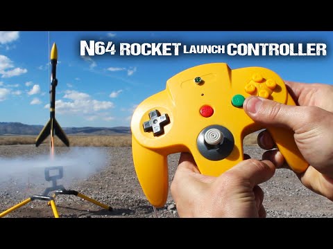
for this project I’m going to show you
how to hack an n64 game controller into
a rocket launch controller little ignite
fireworks up to 30 feet away or launch a
rocket the moment you say so let’s start
this project with a Nintendo 64 game
controller
I chose yellow because this way it’ll
match the randomizer rocket I’ll show
you how to build in another project
video keep an eye out for that now if we
flip the control over you’ll see there
are nine screws holding the two halves
together and all it takes to remove them
is a small Phillips head screwdriver
make sure you save the screws in a
really safe place because we will need
them to put the controller back together
at the end with the screws removed let’s
separate the two halves and take a peek
inside you can see the upper half is the
more complicated side where all the
buttons and electronics are so let’s
just leave that alone for a second and
work on the bottom half instead grab a
pair of pliers and look for the plastic
support where the a button goes then
grip it firmly and tear it off because
we don’t need it while we’re here let’s
rip the top off the housing where the
controller packs go as well it’ll all
make sense in just a second now it’s
really helpful to file and grind down
the little ridges on the inner walls of
the slot and clean up the rough edges
where any plastic got removed it’ll take
a bit of work but when all the walls are
relatively flat and you’ve smoothed down
most of the rough edges you’ll find that
you can push two 9-volt batteries inside
and they fit perfectly that means we can
make an improvised power pack to keep
the whole system portable and
self-contained okay we’re finished with
the bottom half of the controller for
now let’s move over to the top side go
ahead and rip the circuit board right
out of the casing but make sure you keep
all the buttons in a safe place so you
don’t have to waste time looking for
them later
I removed the three small screws to hold
the thumbstick assembly to the casing
and as you
see the whole thing just pops out now in
one piece before we start modifying this
unit there are a few quick adjustments
that need to be made to the underside of
the casing like breaking off the plastic
Ridge right above the start button area
and tearing off the support walls where
the a button used to be this will free
up some space for a few new components
now we also need to drill a couple holes
in the top so I’m using a fifteen sixty
four inch drill bit to cut a hole
directly in the center of where the
Nintendo logo would normally be and a
3/32 inch bit to cut a sound hole just
below that at this point the upper
casing is completely finished so let’s
get back to modifying the thumbstick
assembly only one screw holds the
assembly together we need to be
extremely careful when removing it
because the whole casing is
spring-loaded and they’ll try to burst
open on you it would be a lot easier if
you don’t let that happen
the bottom part of the assembly is where
the trigger button used to be and our
goal here is to replace it with a
momentary push-button switch of course
that means we’ll need to cut a space for
it I tried using a 5/16 inch fit to
carve a channel halfway through the
casing which apparently keeps the
brackets for the circuit board intact
while creating just enough room to
accommodate the button on the inside now
if we dig up the original Z button
circuit board and cut a 5/16 inch hole
straight through the contact pad we
should end up with a hole the right size
for our switch I found this momentary
switch in packs of four at a local
electronics shop we don’t need the gap
or a little tip at the end so go ahead
and snap it off with a pair of pliers
with the switch over and solder
insulated copper wires to each of the
terminals for durability and good
electrical contact when the solder cools
you can see that connecting the button
to the circuit board is as simple as
pushing it through from the underside
and tightening the washer and the hex
nut securely on the top with a circuit
board lock back in place you should be
able to see how this new trigger button
mimics the old Z button almost perfectly
let’s go ahead and replace the joystick
component so we can reattach the
spring-loaded assembly and screw it all
back together with that the modified
assembly is finished so it can go back
into place on the control cover and we
can replace the three screws that hold
it in position now before you do
anything else it’s a good idea to put
the control casing back together and
make sure the new switch aligns with the
trigger button I hooked mine to a
multimeter to be extra sure and test it
for electrical continuity each time the
button was pressed it seems like
everything’s working perfectly so that
means it’s time to load the controller
with a few more goodies you’ll see what
all these do in just a
I found a red push-button that’s an
awesome replacement for the old a button
and this is going to become the ignition
switch for the actual rocket launch it’s
got a plastic nut holding it from the
backside which keeps it tight and helps
prevent it from popping back out the
next step is attaching the buzzer and a
green LED I found that a ring of hot
glue around the center hole is all it
takes to hold the buzzer right where we
need it and of course it works best if
you go line the center up with a small
sound hole we made earlier now you
should find that the sub miniature green
LED makes an excellent fit with the
other hole we made at the top and this
one will need to be held in place with
hot glue as well because there’s no room
for the hex nut just use a liberal
amount of hot glue and when it cools
that LED won’t be going anywhere at this
point all the major components are
installed so let’s solder them together
and bring this launch controller to life
I cut up the cord from an old cell phone
charger and wired everything together
using this schematic I designed the
circuit to run on two 9-volt batteries
in parallel so it has a higher current
the LED and buzzer are set in parallel
as well but only work if the button and
the trigger is pressed when the trigger
is pulled a very small electrical
current will pass through the igniter to
check whether it’s intact or whether
it’s damaged if the connection is good
then the small electrical current
continues to flow through the circuit
lighting up the LED and sounding the
warning buzzer letting you know that the
igniter has continuity and is ready for
ignition
now even though electricity is flowing
it’s only around 40 milliamps and that’s
not near enough to set off the igniter
it actually needs closer to 2 amps or 50
times more power for proper ignition if
you’re ready to launch keep the trigger
pulled and press the red button
simultaneously
this opens the electrical floodgates and
send the surge of around 6 amps through
the igniter firing it off instantly
alright now that the connection points
are soldered and insulated with
electrical tape we just got a few
finishing touches left find the circuit
board you ripped out earlier and draw
two lines one on the bottom side of the
controller pack connection and another
that humps up and over the contact pad
for the a button we can make things a
little more tidy by ripping all the
wires and cords off the board and if we
use a large pair of pliers to grip the
slot for the controller pack and give it
a good twist it’ll snap right off now
carefully break off pieces of the board
around the a button then grind down any
rough edges with a file to clean it up
and make it look
sir find the silicon button pad necks
with the six contacts on it and if you
use a marker to draw a line separating
out where the a button would be then
simply use a pair of scissors to cut it
off then that’s it we can go ahead and
gather up all the buttons now and put
the whole thing back together when the
components are back in place go ahead
and lay the modify button pad in
position now it should make sense why we
had to make that cut the circuit board
goes in next to help keep the buttons
from falling out and to make sure they
look and act like normal now before we
screw the casing together there’s just
one thing left to do and that’s to add
30-foot lead wires so we can ignite the
Rockets from a distance and for that I’m
using a hundred-foot roll of 24 gauge
speaker wire I found at the hardware
store I soldered and taped the wires
into position then tied a knot on the
inside of the casing to protect the wire
from getting pulled out accidentally at
this point let’s feed the two 9-volt
battery clips through the slot for the
controller pack and screw the two halves
back together just like that our n64
rocket launch controller is completely
finished and ready for testing I hooked
up two 9-volt batteries and push them
into place then gathered up a handful of
my homemade rocket igniters which you
can learn how to make in another project
video just for convenience I attached
alligator clips on the ends of each wire
so the leaves will bite onto the
igniters this way we can hook up and
even change igniters within a matter of
seconds now if the electric match has
continuity then when we press the
trigger button a green light and buzzer
come on telling us the system is armed
and ready for launch and pressing the
red button next we’ll light it up and of
course 30-foot lead wires mean we can
remotely launch our rockets now from a
pretty good distance away I took this
launch controller out into the desert to
test on homemade rockets and sugar
motors that I showed you how to make in
another project video you can see that
with everything connected properly the
controller works exactly how we hoped it
would so we don’t have to worry about
lighting a fuse and running away anymore
because instead now we have the ability
to launch rockets or if you like
pyrotechnics with the simple push of a
button well now you know how to convert
an old video game controller into a
remote-controlled rocket launch
controller that not only looks awesome
but watches freaking rockets in real
life by the way if you’re wondering what
to do with the leftover cord from the
controller don’t throw it away instead
use it to mass-produce another round of
igniters for future launches well that’s
it for now if you liked this project
perhaps you’ll like some my others check
them out at the king of random calm
yes hey guys that’s the end of this
video but it’s not the end of the
adventure click here to see the last
project and click here to see the next
I’ve made over 100 project videos for
you to check out and I’m still making
new videos every 5 days so click here to
subscribe to my youtube channel it’s
free and if you update your YouTube
notification settings you can get an
email every time I upload in the
meantime here are a few other videos I
recommend watching they’re all favorites
for different reasons and you’ll learn
something new in every project thank you
for watching sharing and supporting my
videos and I’ll see you in the next
project video I’ll talk to you then
[Music]
how to hack an n64 game controller into
a rocket launch controller little ignite
fireworks up to 30 feet away or launch a
rocket the moment you say so let’s start
this project with a Nintendo 64 game
controller
I chose yellow because this way it’ll
match the randomizer rocket I’ll show
you how to build in another project
video keep an eye out for that now if we
flip the control over you’ll see there
are nine screws holding the two halves
together and all it takes to remove them
is a small Phillips head screwdriver
make sure you save the screws in a
really safe place because we will need
them to put the controller back together
at the end with the screws removed let’s
separate the two halves and take a peek
inside you can see the upper half is the
more complicated side where all the
buttons and electronics are so let’s
just leave that alone for a second and
work on the bottom half instead grab a
pair of pliers and look for the plastic
support where the a button goes then
grip it firmly and tear it off because
we don’t need it while we’re here let’s
rip the top off the housing where the
controller packs go as well it’ll all
make sense in just a second now it’s
really helpful to file and grind down
the little ridges on the inner walls of
the slot and clean up the rough edges
where any plastic got removed it’ll take
a bit of work but when all the walls are
relatively flat and you’ve smoothed down
most of the rough edges you’ll find that
you can push two 9-volt batteries inside
and they fit perfectly that means we can
make an improvised power pack to keep
the whole system portable and
self-contained okay we’re finished with
the bottom half of the controller for
now let’s move over to the top side go
ahead and rip the circuit board right
out of the casing but make sure you keep
all the buttons in a safe place so you
don’t have to waste time looking for
them later
I removed the three small screws to hold
the thumbstick assembly to the casing
and as you
see the whole thing just pops out now in
one piece before we start modifying this
unit there are a few quick adjustments
that need to be made to the underside of
the casing like breaking off the plastic
Ridge right above the start button area
and tearing off the support walls where
the a button used to be this will free
up some space for a few new components
now we also need to drill a couple holes
in the top so I’m using a fifteen sixty
four inch drill bit to cut a hole
directly in the center of where the
Nintendo logo would normally be and a
3/32 inch bit to cut a sound hole just
below that at this point the upper
casing is completely finished so let’s
get back to modifying the thumbstick
assembly only one screw holds the
assembly together we need to be
extremely careful when removing it
because the whole casing is
spring-loaded and they’ll try to burst
open on you it would be a lot easier if
you don’t let that happen
the bottom part of the assembly is where
the trigger button used to be and our
goal here is to replace it with a
momentary push-button switch of course
that means we’ll need to cut a space for
it I tried using a 5/16 inch fit to
carve a channel halfway through the
casing which apparently keeps the
brackets for the circuit board intact
while creating just enough room to
accommodate the button on the inside now
if we dig up the original Z button
circuit board and cut a 5/16 inch hole
straight through the contact pad we
should end up with a hole the right size
for our switch I found this momentary
switch in packs of four at a local
electronics shop we don’t need the gap
or a little tip at the end so go ahead
and snap it off with a pair of pliers
with the switch over and solder
insulated copper wires to each of the
terminals for durability and good
electrical contact when the solder cools
you can see that connecting the button
to the circuit board is as simple as
pushing it through from the underside
and tightening the washer and the hex
nut securely on the top with a circuit
board lock back in place you should be
able to see how this new trigger button
mimics the old Z button almost perfectly
let’s go ahead and replace the joystick
component so we can reattach the
spring-loaded assembly and screw it all
back together with that the modified
assembly is finished so it can go back
into place on the control cover and we
can replace the three screws that hold
it in position now before you do
anything else it’s a good idea to put
the control casing back together and
make sure the new switch aligns with the
trigger button I hooked mine to a
multimeter to be extra sure and test it
for electrical continuity each time the
button was pressed it seems like
everything’s working perfectly so that
means it’s time to load the controller
with a few more goodies you’ll see what
all these do in just a
I found a red push-button that’s an
awesome replacement for the old a button
and this is going to become the ignition
switch for the actual rocket launch it’s
got a plastic nut holding it from the
backside which keeps it tight and helps
prevent it from popping back out the
next step is attaching the buzzer and a
green LED I found that a ring of hot
glue around the center hole is all it
takes to hold the buzzer right where we
need it and of course it works best if
you go line the center up with a small
sound hole we made earlier now you
should find that the sub miniature green
LED makes an excellent fit with the
other hole we made at the top and this
one will need to be held in place with
hot glue as well because there’s no room
for the hex nut just use a liberal
amount of hot glue and when it cools
that LED won’t be going anywhere at this
point all the major components are
installed so let’s solder them together
and bring this launch controller to life
I cut up the cord from an old cell phone
charger and wired everything together
using this schematic I designed the
circuit to run on two 9-volt batteries
in parallel so it has a higher current
the LED and buzzer are set in parallel
as well but only work if the button and
the trigger is pressed when the trigger
is pulled a very small electrical
current will pass through the igniter to
check whether it’s intact or whether
it’s damaged if the connection is good
then the small electrical current
continues to flow through the circuit
lighting up the LED and sounding the
warning buzzer letting you know that the
igniter has continuity and is ready for
ignition
now even though electricity is flowing
it’s only around 40 milliamps and that’s
not near enough to set off the igniter
it actually needs closer to 2 amps or 50
times more power for proper ignition if
you’re ready to launch keep the trigger
pulled and press the red button
simultaneously
this opens the electrical floodgates and
send the surge of around 6 amps through
the igniter firing it off instantly
alright now that the connection points
are soldered and insulated with
electrical tape we just got a few
finishing touches left find the circuit
board you ripped out earlier and draw
two lines one on the bottom side of the
controller pack connection and another
that humps up and over the contact pad
for the a button we can make things a
little more tidy by ripping all the
wires and cords off the board and if we
use a large pair of pliers to grip the
slot for the controller pack and give it
a good twist it’ll snap right off now
carefully break off pieces of the board
around the a button then grind down any
rough edges with a file to clean it up
and make it look
sir find the silicon button pad necks
with the six contacts on it and if you
use a marker to draw a line separating
out where the a button would be then
simply use a pair of scissors to cut it
off then that’s it we can go ahead and
gather up all the buttons now and put
the whole thing back together when the
components are back in place go ahead
and lay the modify button pad in
position now it should make sense why we
had to make that cut the circuit board
goes in next to help keep the buttons
from falling out and to make sure they
look and act like normal now before we
screw the casing together there’s just
one thing left to do and that’s to add
30-foot lead wires so we can ignite the
Rockets from a distance and for that I’m
using a hundred-foot roll of 24 gauge
speaker wire I found at the hardware
store I soldered and taped the wires
into position then tied a knot on the
inside of the casing to protect the wire
from getting pulled out accidentally at
this point let’s feed the two 9-volt
battery clips through the slot for the
controller pack and screw the two halves
back together just like that our n64
rocket launch controller is completely
finished and ready for testing I hooked
up two 9-volt batteries and push them
into place then gathered up a handful of
my homemade rocket igniters which you
can learn how to make in another project
video just for convenience I attached
alligator clips on the ends of each wire
so the leaves will bite onto the
igniters this way we can hook up and
even change igniters within a matter of
seconds now if the electric match has
continuity then when we press the
trigger button a green light and buzzer
come on telling us the system is armed
and ready for launch and pressing the
red button next we’ll light it up and of
course 30-foot lead wires mean we can
remotely launch our rockets now from a
pretty good distance away I took this
launch controller out into the desert to
test on homemade rockets and sugar
motors that I showed you how to make in
another project video you can see that
with everything connected properly the
controller works exactly how we hoped it
would so we don’t have to worry about
lighting a fuse and running away anymore
because instead now we have the ability
to launch rockets or if you like
pyrotechnics with the simple push of a
button well now you know how to convert
an old video game controller into a
remote-controlled rocket launch
controller that not only looks awesome
but watches freaking rockets in real
life by the way if you’re wondering what
to do with the leftover cord from the
controller don’t throw it away instead
use it to mass-produce another round of
igniters for future launches well that’s
it for now if you liked this project
perhaps you’ll like some my others check
them out at the king of random calm
yes hey guys that’s the end of this
video but it’s not the end of the
adventure click here to see the last
project and click here to see the next
I’ve made over 100 project videos for
you to check out and I’m still making
new videos every 5 days so click here to
subscribe to my youtube channel it’s
free and if you update your YouTube
notification settings you can get an
email every time I upload in the
meantime here are a few other videos I
recommend watching they’re all favorites
for different reasons and you’ll learn
something new in every project thank you
for watching sharing and supporting my
videos and I’ll see you in the next
project video I’ll talk to you then
[Music]
Please follow and like us: